Quick-ish update
I am going to keep this on the short side today. I did some more work on the coupling and got rid of the “ears” that were hanging from it. I have some pictures but they’re on my phone and I don’t feel like transferring them over at the moment. There is still a lot of work to do on the coupling, though, and I really need to figure out how or whom to get it done.
I also did some work on the brake pedal. I was reading in the service manual and found out that the device I had marked as the Regen Pot is actually the Brake Pedal Position Sensor. It sounds like if that doesn’t move at the same rate the brake pedal does, the brakes won’t work right. So, I figured out how to mount the sensor on the side of the brake pedal assembly.

The arrows point to the bend in the arm of the sensor and the washer I welded to the brake pedal to capture it. The bracket for the sensor is welded to the assembly and the booger welds ground down enough so they don’t look entirely horrible.

This arrow points to the extra platform I added to catch the plunger of the second switch for the Leaf brake system. To the left you can see the two brake switches. The grey one is the actual brake light switch while the brown one is the “brake position” switch. Above the brake pedal you can see the two holes for the switches. There’s a spring over to the top right that I should see if I can get on there somewhere. It is a return spring that seems designed just to keep the weight of the pedal from pushing on the shaft of the master cylinder.
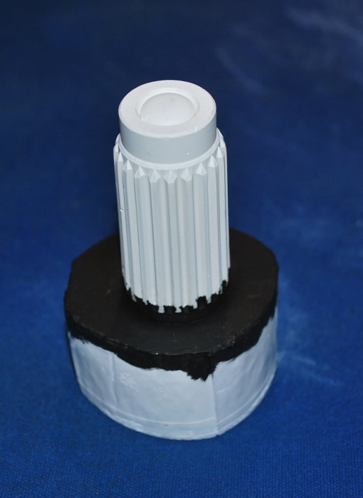
At the suggestion of a friend, I made silicone mold of the motor shaft and then cast it in plaster with an eye toward using it to get an accurate inside spline somehow cut in the coupler. I actually made two of them; the first covers just the splines and the second goes all the way to the face of the motor. The second one isn’t quite round, so I don’t think it will actually be useful. I don’t think I really need it to go that far since the coupling won’t sit that far up.

Side view of plaster cast of Leaf motor shaft. I painted the bottom black to give it more contrast for the next picture. The silicone material I used was sensitive enough that it picked up the lettering ink printed on the side of a bottle. It also picked up all the tool marks on the shaft.

Top View of Casting of Leaf Motor Shaft with the top shaved off. You can see some of the tool marks on the bottom of the picture. I shaved off the top, flat section so I could get a good look at the base of the splines. I will import this into my CAD program and draw lines to match the shape of the splines.
I found the pieces I cut out of the firewall and I’m going to weld them back into place so the brake booster is properly supported. Or, maybe I can talk a friend into doing it since my welding is so barbaric. We’ll see.
I don’t have the CRX fixed up yet, but that is rapidly climbing up my list of things to do. Fortunately, gas is still relatively cheap.
Well, that’s all I have for now. I’ll keep you posted as things progress.
B
You are serious about everything your do. Fabrication is the terrifying part of all this for me you handle it with ease.
Thanks. The part that concerns me is running the high voltage cabling. I’m going to have to spot cells around the car to get them all in and they will all have to be connected somehow.